The insulation resistance is particularly important for the prevention of damage and injury, and for the reliability of electrical systems and equipment. On the one hand it is basis for the protection of individual and systems on the other hand it also serves as an important indicator for the condition of an electrical installation. Depending on the life cycle of a system or an item of equipment, the insulation resistance is to be tested, to be measured or also to be monitored.
Insulation monitoring is not the same as insulation measurement and vice versa. Depending on the related phase of the life cycle of a system or an item of equipment, these two techniques are to be used differently. However, overall it is important that a failure or a hazard for individuals and property is avoided by a preventive action.
The (product) life cycle of an electrical system or an item of equipment can essentially be divided into the phases given in Table 1. Depending on the specific phase, (high) voltage testing, insulation measurement or insulation monitoring are required.
In unearthed power supplies, the monitoring can be undertaken using an insulation monitoring device. In earthed power supply systems the monitoring can be undertaken indirectly using fault current monitoring. By detecting impending insulation faults at an early stage, these devices are an important tool for the timely planning of maintenance tasks.
Conversely, the insulation measurement is only an instantaneous snapshot of the insulation resistance. In principle the insulation resistance is dependent on
Here attention is to be paid to the safety risk and the protection goal.
| Phase of the lifecycle | (High) voltage test | Insulation measurement | Insulation resistance | Fault current | ||
| System not in operation | System in operation | |||||
| IT system IMD | TN/TT system | |||||
| RCD | RCM | |||||
| - | - | Include in planning/ install | |||
| Commissioning | X | X | Adjust/ Test | Test | Adjust/ Test | |
| Operation | - | - | Signal | Shut down | Signal | |
| Maintenance | X)* | X | Signal | Shut down | Signal | |
| Repair | X)* | X | Signal | Shut down | Signal | |
| Major modification | X)* | X | Check/ Include in planning | |||
| Upgrade | X)* | X | Check/ Include in planning | |||
| Decommissioning | - | - | - | - | - | |
X)* As far as required in the standards
Prior to the initial commissioning of an electrical system, in accordance with DIN VDE 0100-600 (VDE 0100-600):2008-06 various measurements are to be undertaken. These include the measurement of the insulation resistance, which is measured between the active conductors and the protective earth conductor connected to earth. During this test the active conductors are allowed to be connected together electrically. The DC measuring voltage and the magnitude of the insulation resistance must comply with the requirements in Table 2.
The insulation resistance is considered adequate if each circuit reaches the required value without electrical loads connected. During the measurement it is to be ensured that all switches in the circuit are closed. If it is not possible to close circuits, the electrical circuits not measured must be measured separately. Any connections between N and PE must be open.
Insulation resistance and measuring voltage in accordance with DIN VDE 0100-600 (VDE 0100-600):2008-06
| Nominal voltage of the electrical circuit (V) | DC measuring voltage (V) | Insulation resistance (MΩ) |
| SELV*, PELV** | 250 | ≥0,5 |
| Up to and including 500V, as well as FELV*** | 500 | ≥1,0 |
| Over 500V | 1000 | ≥1,0 |
*Safety extra-low voltage **Protected extra-low voltage ***Functional extra-low voltage
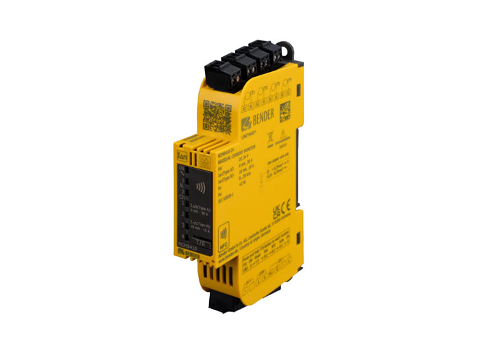
In the case of grounded systems, the insulation resistance is determined indirectly via the magnitude of the fault current. A classic tool for this purpose is the residual current device (RCD), which shuts down the system or the loads if a certain fault current is exceeded and is this way prevents a hazard. In areas in which a shutdown could be a problem for operations, e.g. IT systems, often residual current monitors (RCM) are used.
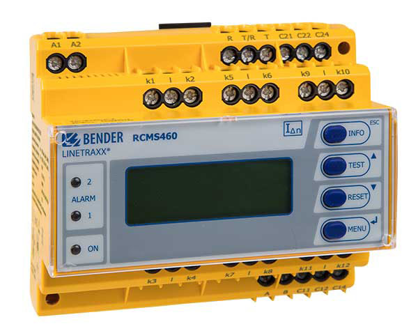
These also operate based on the residual current principle that is the difference between the current flowing in and out is measured using a measuring current transformer and a signal provided or the system shut down at a specific fault current. Depending on the related fault current, AC, pulsed DC or AC/DC sensitive devices are used. For systems in which a large number of outgoing circuits need to be monitored, multiple channel systems are also available on the market, so-called RCMSs.
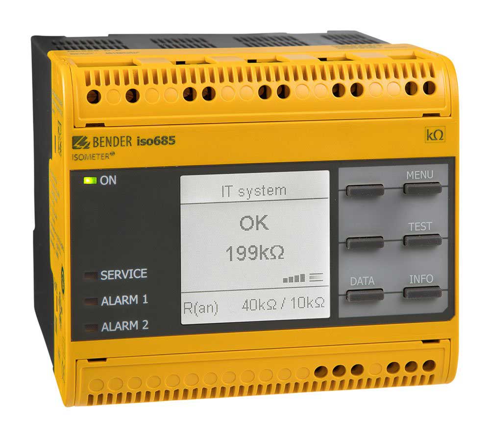
Unlike TN/TT systems, in IT systems the active conductors are insulated from ground. In these systems the insulation resistance between the active conductors and ground is continuously monitored with the aid of a ground-fault monitoring device (IMD).
If the value measured is below a specific resistance (kΩ ) an alarm is output. Here a key advantage of the IT system becomes clear. In accordance with DIN VDE 0100-410 (VDE 0100-410):2007-06 shut down is not necessary on the occurrence of a first fault such that operation can continue uninterrupted. This aspect is of crucial importance in safety-related areas, e.g. in hospitals, industrial plants or electric mobility.
As the IT system supplied is in operation, the ground-fault monitoring device measures the total insulation resistance of the system, including all loads switched on that are electrically connected to the IT system.
The response value required for ground-fault monitoring devices is given in various installation requirements. In practice a value of 100 Ω/V for the main alarm and 300 Ω/V for ground-fault monitoring devices with a pre-warning stage have been proven appropriate.
Alternatively the response value can be set to a value that is 50 % higher than the value required in the standards.
It is also possible to adjust the response value to suit the requirements of DIN VDE 0105-100 (VDE 0105-100):2009-10 (see Table 3). Here it is the responsibility of the planner or the installer of the system to draw on appropriate experience.
In some areas there are loads that are disconnected for a time, e.g. fire extinguishing pumps, valve drives, lift motors or emergency generators. While they are switched off, moisture or other effects can cause insulation faults in the supply cable or in the load itself and these faults go unnoticed. In these cases offline monitors are used. More information about offline monitoring can be found here.
| Name | Category | Size | Language | Timestamp | D-/B-Number |
|---|---|---|---|---|---|
| Gama de Productos ISOMETER®/ISOSCAN® | Product Overviews | 3.8 MB | ES | 2022/05/2525.05.2022 | |
| Why the IT System is Often the Best Choice for Power Supply Systems of All Types | Technical Article | 3.0 MB | EN | 2019/07/1111.07.2019 | |
| High Availability for Reliable Operation in Waste Water Treatment Facilities | Technical Article | 601.8 KB | EN | 2019/05/1313.05.2019 | |
| IT System Ensures Electrical Safety at the Munich Airport | Technical Article | 284.0 KB | EN | 2019/05/1313.05.2019 | |
| The Stone Age Meets Modern Network Protection Technology | Technical Article | 338.5 KB | EN | 2019/05/1313.05.2019 | |
| The Largest Photovoltaic System in Latin America | Technical Article | 447.8 KB | EN | 2019/05/1313.05.2019 | |
| Verificación inicial y revisión de sistemas IT | Technical Article | 634.8 KB | ES | 2022/06/1010.06.2022 |
Products

Ground-fault detector for ungrounded AC/DC systems

Ground-fault location module for ungrounded AC/DC systems
Ground-fault detector for ungrounded AC/DC systems
Ground-fault location module for ungrounded AC/DC systems